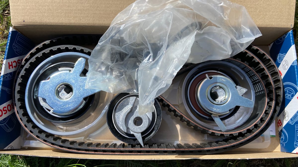
VIDEO PART 2 - Install new Injection toothed belt with new tensioner and new idler roller and set injection pump on VW T4 ACV 2.5TDI 75KW

Prerequisites
- Marks -arrows- on injection pump pulley/bracket -C- and flywheel/
clutch housing -A- or drive plate/clutch housing -B- must
align (This condition is only achieved every 2nd TDC - top dead center - position.)
Job
- Check whether TDC mark on flywheel and reference mark are
aligned. - Fit toothed belt onto injection pump pulley.
- Fit injection pump drive pulley into toothed belt and secure
gear on camshaft so that the gear can still turn.
Install idler roller
- Install idler roller -1-.
- Turn idler roller so that indicator aligns with flange contour of
cylinder head -arrow-. - Tighten securing nut -2- to 20 Nm.

Install belt tensioner
- Install belt tensioner -1- so that belt tensioner tab seats in cutout
on bracket -arrow B-. - Tighten securing bolt hand-tight.
- To tension toothed belt, turn belt tensioner anti-clockwise until
both indicators are aligned -arrow A. - Tighten securing bolt to 15 Nm.
- Tighten injection pump drive pulley securing nut to 160 Nm.
- Use counterhold tool -3036- for this.

- Loosen locking bolt -2- on injection pump.
- Insert intermediate plate -1- and tighten locking bolt to 12 Nm.
- Turn crankshaft two rotations in engine direction of rotation
until crankshaft is set to TDC No. 1 cylinder again.

Check
- The marking on the injection pump pulley must align with the
marking on the injection pump -arrows-. If injection pump pulley
marking is not visible, turn crankshaft one turn further. - Check position of indicators -arrow A- on the belt tensioner. The indicators must align. If the indicators do not align, but the front indicator is
located within the underlying sheet metal contour, this is permissible.

Fine tune injection pump timing with clock
- Screw in the injection pump adapter 3313 instead of plug.
- Insert dial gauge (clock) (measuring range 0...3.0 mm) into adapter
with pre-tension of approx. 2.0 mm. - Check that mark on injection pump pulley and injection pump
are aligned (picture above v23-0324). - Loosen locking bolt -2- on injection pump
- Remove underlying intermediate plate -1-.
- Set dial gauge to “0”.
- To ensure the injection pump high-pressure pistons are at
BDC, turn injection pump pulley slowly counter to engine direction
of rotation (clockwise) using counterhold tool -3036- .
The dial gauge indicator must remain at “0”, reset dial gauge
to “0” after reaching BDC if necessary - Turn injection pump pulley slowly in engine direction of rotation
(anti-clockwise) until dial gauge indicator shows 0.55 mm
stroke using counterhold tool -3036- . - Tighten locking bolt to 30 Nm.


